Fully enclosed lifeboats, solas. Lifeboats (enclosed) Enclosed lifeboats
The lifeboat is the primary active collective life-saving device designed to rescue the crew and passengers. On newly built ships, as a rule, lifeboats should be of the self-repairing type, fully enclosed and motorized. Their motors must be capable of mechanical and manual starting, run or automatically shut down (and then easily start) upside down. Boat speed in calm water with complete set people and supplies must be at least 6 knots. For vessels in service, the temporary use of non-self-recovering, open and semi-closed lifeboats is allowed. The lifeboats of a cargo ship must ensure the landing of a full number of people in no more than 3 minutes from the moment the landing command is given, as well as quick disembarkation of people from the boat.
Lifeboats for oil tankers are made fireproof. When the water sprinkler system is working, they can withstand the effect of the flame of continuously burning oil for at least 8 minutes when the boat passes the fire zone on the water. These boats are equipped with a compressed air system that ensures the safety of people and the smooth operation of the engine for at least 10 minutes. In fig. 1 shows the domestic AT-30 tanker boat.
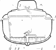
Fig. 1 Tanker boat AT-30:
a) appearance: 1 - stripes of reflective material; 2 - crosses made of reflective material; b) irrigation system: 3 - slotted heads; 4 - a system of pipes for irrigation of the boat, 5 - a pallet for collecting the flowing water after irrigation of the boat before launching it into the water, 6 - Kingston hinged branch pipe; 7 - pump, 8 - three-way valve, 9 - ballast compartment;
10 - capacity between the bottom of the boat and the pallet
The lifeboats are painted orange on the outside. In the bow, on both sides of the boat, inscriptions are made in Latin letters indicating the name of the vessel, the port of registration, the size of the boat and the number of people allowed to be accommodated. Outside the lifeboat, a floating life line is fixed with sags. Reflective strips are glued along the perimeter of the boat under the fender bar and on the closing deck. Fore and aft
parts of the boat on the upper part of the cover are glued with crosses made of reflective material.
The number of lifeboats on board the vessel is determined by the area of navigation, the type of vessel and the number of people on the vessel. Cargo ships of unlimited navigation area have lifeboats providing 200% of the ship's crew (100% from each side). Passenger ships have lifeboats on the basis of providing 100% of passengers and crew (50% from each side).
The location of the boats must ensure their preparation for launching in no more than 5 minutes; landing and descent in 10 minutes on a cargo ship and no more than 30 minutes on a passenger. Well distinguishable and compliant with IMO recommendations, conventional signs, signs, symbols should be applied near lifeboats and on escape routes. The gathering place and the landing site must be connected to the command post by two-way loudspeaker communication.
The launching device must ensure the launching of the lifeboat with a roll of 20 and a differential of 10 ° at a vessel speed of up to 5 knots. Provision shall be made for the control of the launching of the lifeboat from the lifeboat, as well as a device for simultaneously releasing the hooks of the davits under load.
The traditional lifeboat launching device is gravity davits. The launch of the lifeboat occurs under the influence of its weight when the brake of the davits is released. When using closed boats, the brake lever is connected through a system of blocks with a cable to the handle inside the boat. The special design of the launching of the release cable from the drum through the brake lever and through the blocks ensures its release synchronously with the release of the davits and the launching of the lifeboat. This allows the speed of descent from the lifeboat to be adjusted.
Lifeboat supply
All lifeboat supplies should be lashed inside the lifeboat, stored in boxes or compartments, mounted on brackets or similar fixtures, or otherwise secured in an appropriate manner.
However, if the launching of the lifeboat is carried out on hoists, then the boat hooks must not be secured so that they can be used to push the lifeboat away from the side of the vessel. Supplies should be secured so that they do not interfere with abandonment operations. All lifeboat supplies should be as small and light as possible, and they should be conveniently and compactly packed.
Except where otherwise specified, the normal equipment of each lifeboat should include:
1 with the exception of free-fall boats, a sufficient number of buoyant oars to enable the boat to move in calm water. Each oar must be provided with a cochet-type oarlock, swivel oarlock or other equivalent device. The oarlocks must be fastened to the boat with braids or chains;
.2 two striking hooks;
.3 a floating scoop and two buckets;
.4 life-saving instructions;
.5 a compass illuminated or adequately illuminated. In fully enclosed lifeboats, the compass should be permanently mounted at the helm position; on all other lifeboats, the compass must be in the binnacle if weather protection is required and must be properly secured;
.6 a buoyant anchor of sufficient size with a jerk resistant anchor that allows a firm grip when wet. The strength of the floating anchor, directing and nyral, if provided, must be sufficient in all sea conditions;
.7 two reliable painters of a length not less than twice the distance from the position of the lifeboat to the waterline at the lightest operating draft of the ship, or 15 m, whichever is greater.
In free-fall lifeboats, both painters must be in the bow of the boat and ready for use.
On all other boats, both bows must be ready for use, and at the same time one must be fixed to the release device, and the other firmly to the stem or near it;
.8 two axes, one at each end of the lifeboat;
.9 watertight receptacles containing a total of 3 liters of fresh water for each person permitted to be accommodated on a lifeboat, of which 1 liter of this rate per person can be replaced by water obtained from a desalination apparatus capable of producing the total fresh water within two days, or 2 liters of this norm per person can be replaced with water obtained from a hand-operated desalter capable of producing the same amount of fresh water within two days;
.10 stainless steel ladle with pin;
.11 stainless graduated drinking vessel;
.12 food ration with a caloric value of at least 10,000 kJ for each person from the number of people allowed to be placed on the lifeboat; the food ration should be in air-tight packaging and kept in a waterproof container;
.13 four parachute rockets;
.14 six hand flares;
.15 two floating smoke bombs;
.16 one waterproof electric torch suitable for Morse code signaling, with one spare set of batteries and one spare bulb in a waterproof case;
.17 one daytime signaling mirror with instructions for its use for signaling to ships and aircraft;
.18 one copy of the table of the life-saving signals referred to in regulation V / 16 of the Convention, watertight or watertight;
.19 one whistle or equivalent sound signal;
.20 a first aid kit in a waterproof container that can be closed tightly after opening;
.21 medicines from seasickness in an amount sufficient for at least 48 hours and one hygiene bag for each person;
.22 a folding knife attached to the lifeboat with a string;
.23 three can openers;
.24 two buoyant life rings attached to a buoyant line of at least 30 m in length;
.25 a hand pump of adequate capacity if the boat is not a self-draining type;
.26 one set of fishing tackle;
.27 a sufficient number of tools to make minor adjustments to the engine and related devices;
.28 portable fire extinguisher of an approved type suitable for extinguishing oil fires;
.29 a floodlight with a horizontal and vertical beam sector of at least 6 ″ and a measured light intensity of 2500 cd, capable of illuminating continuously for at least 3 hours;
.30 an effective radar reflector if no radar transponder is installed in the lifeboat;
.31 thermal protective equipment in an amount sufficient for 10% of the number of persons permitted on a lifeboat or two, whichever is greater.
In port cities, among the recreational and tourist amateur ships, you can always see a lot of boats, or even yachts, converted from outdated ship's boats. Most of them hung on the davits for ten or fifteen years; they were warmed by the tropical sun, covered with an ice crust in the northern seas, thrown by a wave against the ship's side, watered with showers, and now the stern inspector of the Maritime Register, at the next examination of the life-saving appliances, finds defects, the boat can no longer be considered absolutely reliable.
But the ship's crew in case of an accident will be forced to entrust their lives to her! And this can happen in the most difficult conditions - in a stormy sea, far from the coast, or vice versa - on a brutal surf wave. There are doubts about the reliability - it means that the sea service is over! (and many boats are generally "written off" to the shore only because they are being replaced by more advanced ones - plastic, motorized.)
In a calm environment - on the river or in the bay - the same old boat, turned by an amateur into a pleasure boat, can still serve for many years. The new owner of the boat may take his time to make repairs that are not allowed or deemed inappropriate for the ship's life-saving appliances. For example, to eliminate the leakage of the cracked skin by pasting the body with fiberglass; change worn-out singing casing; install duplicate frames next to the cracked ones.
It's worth the work! After all, having repaired a decommissioned boat, an amateur shipbuilder receives an obviously seaworthy and durable hull with a large internal volume, which can be rationally used to equip a comfortable cabin and all the necessary premises of a displacement pleasure-tourist vessel.

It will take much less materials to purchase than when building a new ship. All work can be performed outdoors - under any cover or canopy, and most importantly, work on the interior furnishings no longer require such a high qualification of the performer as the construction of the building itself. However, it would be a mistake to think that a person who, on his own, converts a boat into a boat (or, moreover, a yacht), does not encounter difficulties.
There are many of them. They are explained by the specific purpose of the lifeboat, which should, first of all, accommodate as many people as possible in an accident (there is no time for convenience!) And give them the opportunity to hold out until the rescuers approach (to develop high speed is not required!).
Now you have to remove the transverse and longitudinal banks, air boxes; cover the bow with a deck and mount the wheelhouse; take care of ensuring sufficient draft and deepening of the propeller with a relatively low load, which will have a pleasure boat; it is not uncommon for an amateur to adapt a pure rowboat to accommodate the engine and fuel tanks.
The number of design problems increases sharply if you want to get a motor-sailing vessel: it is far from easy to ensure stability and good controllability when sailing, to reduce drift on sharp courses. How do amateur shipbuilders deal with these problems? This is what our next review is devoted to.

0 conversion of old boats into yachts was reported in the 30th issue of the collection ("Asmodey" from a 6.7-meter boat and "Au-ra" from a 7.8-meter work boat), 9th issue (a yacht from a 10-meter longboat), 3rd release (yacht from a 6.1-meter yala - "six"). Two options for converting the "six" into a boat and a motor-sailing vessel are considered in the 5th issue. Articles will also be useful: "A boat must be beautiful" (issue No. 7), "Motor-sailing yachts" (issue No. 9), "Leisurely boats" (issue No. 18) and other materials.
Former naval boats (yalas) also quite often begin a second life, falling into the hands of amateur shipbuilders. In 1969 Irkutsk nautical club DOSAAF handed over to MA Zubovich the out-of-date YAL-6 of 1955 release for restoration. Time had an inexorable effect on the hull of the boat: many of the frames were broken, the planks were cracked.
Old rusty patches and remove a thick layer of putty and paint accumulated over many years of operation (no scrapers helped, the paint was annealed with a blowtorch). The entire outer surface of the case was sanded, and then pasted over with glass cloth in three layers.
In the wheelhouse area, three frames with a section of 50 X 60 were additionally installed in the hull of the boat, at a distance of one meter from one another. The upper ends of the ribs protruded above the fender by 450, 375 and 300 mm, thus forming the basis for the installation of longitudinal coamings of the deckhouse.

The beams of the felling are cut into a thorn on the protruding ends of the frames and fixed with bakelized plywood knobs on galvanized screws. Beams and frames under the mast standers are reinforced. The second and third cans, which ended up within the cabin, were removed by M.A.Zubovich.
In a cabin with dimensions of 1.8 × 2.0 m, he installed two locker-seats, between which there is a passage with a width of 350 mm in the bow and 550 mm in the stern. The floor covering the hold in this aisle at night rises to the level of the seat and a solid bed is obtained, on which the entire crew of four people can freely fit across the boat.
A stationary engine "L-12" is installed on a foundation made of wooden beams, long-term operation of which on many low-speed boats has created a stable reputation for it as reliable and economical. Outboard water is supplied to the cooling system by pressure from the side of the discharge surfaces of the propeller blades. Before being thrown overboard, hot water is passed through a radiator that heats the cabin in the autumn.
The engine is closed from above by two hinged covers, which serve as the aft deck. The engine shaft is connected to the propeller shaft through the hoist cardan from the ZIL-585 dump truck. The shaft extends beyond the transom 275 mm above the keel line. The screw is protected from below by a spur (ski) made of a steel channel; the steering wheel thrust bearing is also fixed on it. This ensures that both the propeller and the rudder remain intact when the boat is run aground.

The engine is equipped with a generator with a relay-regulator from a Moskvich car, which operates on a 12 V battery. The device allows power to be supplied to the lighting system and navigation lights, a receiver and a tape recorder. (The generator was installed according to the drawings and materials given in the collection No. 9.)
The bow compartment - from the stem to the first can, is closed by an airtight bulkhead and is used to store the sails. The mast is placed on a metal stand on the roof of the wheelhouse. The standard armament of the yala has been replaced by more effective armament from the "Flying Dutchman" class dinghy, however, when tacking under sails, the boat has a strong drift, since the lateral resistance area of the underwater part is insufficient.
Since the "Rose of the Winds" is a motor-sailing vessel, such a disadvantage, according to M. A. Zubovich, is quite possible to put up with. The ship goes well in backstay and fordewind. Considering that the vessel is used for sailing on Lake Baikal, where it is sometimes very difficult to find fuel, the possibility of using sails on some passing courses already seems to be a considerable advantage - it allows you to save gasoline, and sometimes just take a break from the engine noise.

Here is what M. A. Zubovnch tells about his first trip on the "Rose of the Winds":
“It was back in 1968. We went out into the lake in calm weather, towing a Kazanka loaded with fuel and other equipment. The crew consisted of four people. With all this, the average speed under the engine was about 7 knots, which was fine for us.
In long-distance tourist trips, the main thing is reliability and safety! Two hours later, a light southeasterly wind blew - kultuk. The wind quickly gained strength. We set the sails and turned off the engine - the boat was heading north at a speed of about 5 knots. Ten hours later we were on the way to Peschanaya Bay.
On the crossing, we had to use the patent reef, reducing the area of the mainsail, since we were heavily heeled when the wind gusts. The vessel, even when heeling, did not take on the water. We passed the next stage to the Olkhonskiye Vorota under a motor: one could afford such a "luxury", since there is a gas station in the village.
Having stocked up there gasoline, we headed for Nizhne-Angarsk. The distance of 600 km was covered in six days. And in total, during the first voyage, about 2000 km were covered. In order to save fuel, the slightest possibility of sailing was used. During many years of operation, the "Vetrov Rose" has shown excellent seaworthiness.

The use of a sailing rig in combination with a motor makes it possible to make very interesting sailings over long distances. " MA Zubovich used highly efficient sailing equipment from a modern racing sailing dinghy, however, on a vessel not equipped with any devices to counteract side drift - drift, of course, it was not possible to realize the high qualities of Bermuda sails.
Moreover, the high windage with this type of armament also led to the appearance of a large roll with increased wind. (You can see that as a result of alterations, the stability of the boat has deteriorated: the deck in the bow, the structure of the wheelhouse, the gas tank of a solid capacity - are located high and, accordingly, increased the center of gravity of the vessel.)
Therefore for similar cases using sails as an aid - mainly in fair winds - more comfortable armament with sails of the Latin, gaff type or guari is strongly recommended. These sails have a lower center of wind pressure than Bermuda sails of equal area; accordingly, the vessel will heel less in the fresh wind.
Lighter spars and lower mast height are also the advantages of the slab and rack armament; this not only simplifies the manufacture of the mast, but is also important when sailing on inland waters paths when you have to pass under numerous bridges and power lines.

Generally speaking, on motor sailing. ships sailing mainly along rivers can be content with an even simpler type of weapon - with straight sail, bribock. All the same, against the wind and the current, tacking under sails is tedious, and sometimes simply impossible; on the same winds, the brief is good.
The straight sail arrangement is fairly well known. Rey is lifted up with a halyard attached to the middle of the halyard with a rax-rope that slides over the mast. To set the sail at the desired angle to the center plane of the vessel, there are throws drawn from the cockpit to the ends - the legs - of the yard, and sheets, which, for the convenience of sailing, are best carried out, as shown in the sketch.
With its middle the sheet is attached to the lower corner of the sail, one end of it (it is, strictly speaking, a tack) is passed through a guide lining or a block located at the side in front (about 0.5-0.7 m) of the mast, the other end (actually sheet) - through the same edge behind the mast. From the windward side, the “tack” wraps around the front luff of the sail, and from the leeward side, the “sheet” is selected so that the sail does not rinse with the wind.
With such an armament, the cables should be sufficiently carried to the stern so that they do not interfere with the turn of the yard and more reliably loosen the mast from the rear. Along the way, there are several recommendations for choosing the size of the brief. The mast is usually made in height (from the deck or roof of the wheelhouse), approximately equal to half the length of the boat. The width of the sail along the leech is taken to be equal to the breadth of the vessel, and the upper sail (along the yarn) may be slightly larger.

On the "Rose of Winds" quite a lot of space is occupied by the "engine room" - the engine is installed far from the sternpost. It would be possible to move it a little aft and gain additional cockpit space if the author applied a different foundation design.
An original solution is proposed by EK Likhushin (from Kuibyshev), who also used the body of the old "six". Since it is very narrow in the stern itself, it turned out to be impossible to install the engine on the longitudinal sub-engine beams in the usual way. EK Likhushin fixed these beams to the frames not below, as usual, but above the engine paws in a plane parallel to the waterline.
The horizontal angle between the bars was about 30 °, and the space between them was sufficient to accommodate the engine. The engine feet are supported by two welded trapezoidal brackets (made of steel squares) fixed to the longitudinal rails.
The stern seat had to be lengthened in the bow by 150 mm; for servicing the motor, a hatch is cut in it, closed by a cover; here, under the seat, there is also a gas tank. E. K. Likhushin retained the standard rudder nib. It was necessary to cut it (as well as the stern post bar) to accommodate the screw very little. This was achieved thanks to the displacement of the steering pins from the rod.

As a successful example of solving the issues of architecture and internal planning of yachts equipped with lifeboats, one can name a 5.5-meter yacht built by Leningrader M. N. Bogdanov (general drawings were developed by A. B. Karpov). The sides of the boat are built on with a wide belt made of bakelized plywood: the width of this belt is 300 mm at the stem, and 360 mm at the stern. The upper part of the cabin is designed in the form of a forecastle - a superstructure extending from side to side along the entire width of the hull.
The side walls of the superstructure are installed with an inward inclination of 8-10 °; at the extremities they are vertical and are attached to the bars with which the pins are built up. The result is a spacious, wide cabin with a sufficient height "in the light" (1.3 m) with a slender silhouette of the yacht. Coloring of the superstructure in a dark color, which differs from the color of the side, is subordinated to aesthetic perception; a powerful oak bead also separates these surfaces, visually reducing the overall height.
Another advantage of the version with a forecastle is a spacious deck, comfortable for work and rest. The support of the mast step is a semi-bulkhead that divides the internal volume into two rooms - two cabins. The bow cabin has a wide double sofa bed, and wardrobes are located to the side of it on the starboard side. The cover of the forelug (its size is 500 × 400 mm) is made of thick plexiglass.
In the layout of the aft cabin, the designer also moved away from the traditional symmetrical arrangement of sofas. On many lifeboats, the keelson, laid in the DP on top of the frames, protrudes above them and above the floorboards to a height of up to 100 mm and, with a symmetrical layout, turns out to be underfoot; usually the height of the cabin has to be increased further because of this.

In this case, the keelson does not create any inconvenience, since it turned out to be on the side of the main passage. The table on the port side can be lowered to the level of the seats to create a one and a half berth. The cockpit is self-draining (since its bottom is only 200 mm above the waterline, drain scuppers must be equipped with non-return valves, for example, float type).
The engine is installed in an afterpeak separated by a watertight bulkhead and is serviced through a hatch in the deck. An interesting version of the conversion of a 7-meter lifeboat into a sailing-motor yacht was carried out by the Leningrader A. Tabachnik.
All air boxes and cans were removed from the hull, practical things and gunwale were removed. After removing the old paint, defects were found in the skin made of strips of bakelized plywood. The tongue-and-groove belt suffered the most - the groove along the keel was leaking heavily. However, this belt was not replaced, but the groove was sealed by placing a triangular patch rail on canvas and oil putty here (see sketch).
The damaged areas of the plating on the pins were covered with linings of 1-2 mm brass. The places repaired in this way absolutely did not let the water through. The future yacht was supposed to sail in the Ladoga and Onega lakes, known for their turbulent nature, so the need to install a heavy false keel and equipment for a self-draining cockpit did not cause doubts among the participants in the construction of the vessel.

To fasten the 500-kilogram false keel, nine pine forests 60 mm thick were installed on the bottom, and powerful keel bolts were passed through five of them. Floras are cut into keel and skin, and a regular keelson is laid on top of them. The motor foundation is a welded structure consisting of two steel floors connected by longitudinal beams from a 45X45X5 square.
The minimum height inside the cabin was chosen - 1450 mm from the floor. Thanks to this, the wheelhouse turned out to be low, well in harmony with the hull and not having a negative effect on the seaworthiness of the vessel. They decided to arm the yacht with a two-masted Bermuda schooner. This made it possible to obtain a significant total sail area (about 30 m 2) with a relatively low position of the center of the sail.
In addition, the distribution of the sail across the two masts allows using different options for carrying sails depending on the specific sailing conditions and improving the turnability of the vessel: after all, boats with their long keel are "not very willing" to make turns, especially in strong winds.
However, these basically correct calculations of the builder in this case were not fully justified. The ship is heavily driven under full sail; small Bermuda sails operate ineffectively on it (in particular, due to harmful mutual influence). In the future, it was decided to re-equip the yacht with an ordinary sloop with a large genoa.

In the very first cruise along restless Ladoga, the ship demonstrated high stability. It is equipped with a water-cooled two-cylinder gasoline engine that develops 20 hp. With. at 3000 rpm. To do without a reversing clutch to ensure reverse and idle speed, the builders of the yacht made a three-blade adjustable-pitch propeller (drawings by A.P. Shirshov were used, published in the 10th issue of the collection).
The speed under the engine was 7 knots. The dimensions of the engine room did not allow using the handle to start the engine, so a starter had to be installed from the Moskvich-408 car, and the flywheel was replaced with another - with a gear ring (from Zaporozhets engines). The storage battery is charged from a 300-watt generator from the GAZ-21 engine.
Water is supplied to the cooling system by a two-section pump, in the design of which impellers from the outboard motor "Moscow-25" are used. From this the same the motor is also equipped with a fuel pump. The fuel supply is stored in two standard airboxes of the boat with a total capacity of 80 liters.
Naturally, with an increase in the size of the boat, there are more opportunities to make the future boat or yacht more comfortable, it is better to adapt them for long voyages. For example, in the project of re-equipment of a 10-meter rowing boat into a motor-sailing yacht, made by D.A. with six berths.


Four-cylinder diesel engine "4ChSP8.5 / 11" with a capacity of 23 liters. With. gives the yacht a speed of 6.5 knots. It is installed in the stern itself, under the cockpit, and is closed by the hood. The helmsman's post is protected by a wheelhouse open from the stern, which also serves as an entrance vestibule. The two fuel tanks located under the cockpit platform have a total capacity of 360 liters and provide a cruising range of 450 miles under the engine.
The galley is located directly at the entrance, due to which the room is well ventilated when the companion hatch is open; the pitching amplitude in the middle of the vessel is small - this contributes to the successful work of the cook at sea. The forepeak is used as a sailing storage and sleeping quarters for three crew members.
Forluk with a porthole mounted in it has increased dimensions for the convenience of working with sails. The mess-room, in addition to the windows in the wheelhouse coamings, is illuminated (and ventilated) through the upper light hatch. The yacht is designed for combined navigation with an exit from inland waters into the sea, therefore, the vessel is equipped with a gaff tender with a retractable topmast.

By changing the sails on a tender, you can effortlessly "follow" changes in the wind and vary the sail area within a very wide range. With a fresh wind at sea, the yacht will be able to sail only under a working staysail and a mainsail (total area 41.5 m 2), having a sail center position 600 mm forward from the center of lateral resistance.
The cleaver increases the overall windage by 12 m 2; the vessel will also be able to sail steeply to the wind. With a topsail, the total sail area increases to 61.5 m, but this option, of course, is acceptable only in light winds (it can be very useful when sailing in such conditions when it is important to use a riding wind).
This vessel will not be a good tacker: this would require a more efficient and deep keel, unsuitable for the given sailing conditions (draft is limited) and, moreover, much worsening the driving performance under the engine. A compromise option is proposed with a 500 mm high false keel-fin, made, as usual, in the form of a welded steel box filled with scrap metal and cement; this false keel is attached to the reinforced floras through the keel with M18 - M20 bolts.

Its weight is 1200 kg, and the total displacement of the yacht is about 5 tons with an overall draft of 1.4 m.Of the details of the project under consideration, it is worth noting a stylized clipper-pin in the form of an attachment to the boat's standard stem, and a bowsprit, which is a wide inclined platform, which will be convenient, for example, when setting the jib or mooring to a high wall.
Marine lifeboats subdivided:
By body material - metal (steel or aluminum-magnesium alloys), wood (type-setting or glued) and plastic;
By the type of propulsion unit - oar, sailing and propeller driven (driven by a motor or with a manual mechanical drive);
The shape of the hull is of a whaleboat type, with a transom stern, open and hermetically sealed;
By size.
The dimensions of the boats (Fig. 269) are regulated in accordance with the requirements of the International Organization for Standardization (ISO). The range of lifeboats is based on the minimum ratio of their gross volume to the product of basic dimensions LxBxH not less than 0.64. For a wooden boat, this ratio can be at least 0.6 with a decrease in the number of people accommodated in it.
Standard sizes of domestically produced lifeboats are set depending on the capacity, hull material and propulsion type.
For example, boats USAM-48, USAR-48, SSHPM-48 and SSHPR-48 are designed for 48 people each, have a length of 7.5 m, a width of 2.7 m, a midship depth of 1.1 m, a mass with people and supply 5.5 t (letters mean: WITH- rescue, Sh- boat, A- made of aluminum-magnesium alloy, P- plastic made of fiberglass, R- With manual drive, M- motor, T- tanker).
Domestic-made tanker lifeboat UST-30 (Fig. 270, 271) has a capacity of 30 people, length 8.6 m, width 2.6 m, side height 2.3 m, weight with supply 2.9 t, speed 6 , 2 knots It is made of light alloy, sealed, has hatches for the crew and one more hatch at the ends for access to the lifting hooks. High freeboard, water-gas-tight closure ensure the stability of the boat and protect the crew from water, fire and gas.
The requirements for the design of lifeboats are set out in SOLAS-74 and the Rules of the Russian Register. A lifeboat, which carries the full number of persons for which it is designed and has the necessary equipment, must maintain positive stability and an adequate freeboard.
The length of the lifeboat must not be less than 7.3 m, unless the installation of such boats is not feasible due to the size of the vessel or for other reasons. In such cases, the length of the boat can be reduced to 4.9 m... The mass of the lifeboat with people and equipment should not exceed 20 T, and the capacity is no more than 150 people.
Lifeboats with a capacity of 60 to 100 persons should be either motorized or mechanically driven by a propeller. Boats with an installed capacity of more than 100 persons must be powered only.
The buoyancy must be sufficient to keep the lifeboat and its supplies afloat when filled with water and open to the sea. In addition, a buoyancy reserve must be provided through the additional volume of waterproof air boxes. The volume of air boxes must be at least 0.1 of the gross volume of the boat. The internal buoyancy of a power-driven lifeboat or motorized lifeboat must be increased to compensate for the weight of the power-driven or motorized lifeboat.
The number of persons that can be accommodated on a lifeboat is equal to the largest whole number obtained from dividing the volume of the lifeboat (in m 3) by the number 0.283.
The Register Rules establish additional requirements for the construction of fiberglass boats, motor boats and power-driven boats with propeller-driven propellers.
The hull of the lifeboat made of fiberglass (Fig. 272), as well as the hull of the lifeboat made of light alloy (Fig. 273) must withstand the load without being damaged or undergoing permanent deformations when it hits a rigid vertical wall with a span of 3 m, or when it is dropped into water at full load from a height of 2.5 m.
Power lifeboats shall be equipped with a reversing motor capable of reverse propulsion. The engine power must be such as to ensure a forward speed in calm water of at least 6 knots for passenger boats, oil tankers and fishing vessels, and at least 4 knots for lifeboats of other types of vessels. The fuel reserve must provide the engine operation for at least 24 hours in running mode. The engine must be manually operated for 1 minute under any conditions possible during the operation of the vessel.
Power-driven lifeboats (Fig. 271) with full supply and a regular number of people must have a drive that develops power sufficient to ensure that the boat could pass a distance of at least 150 m in calm water from the "Stop" position in the first two minutes, and on a steady course - in 4 minutes a distance of at least 450 m (have a speed of about 3.5 knots).
The lifeboats of oil tankers must be made in such a way that they can withstand exposure to a flame with a temperature of at least 1200 ° C for at least 10 minutes. While the boat passes the fire zone on the water, the temperature inside the boat must not exceed 60 ° C for at least 5 minutes. The boats must be designed so that they come back to normal from any position. The launching control of the tanker boat must be from inside the boat. The boat must be equipped with a compressed air system that ensures the safety of people and the smooth operation of the engine for at least 10 minutes.
The lifeboat is painted and marked with bright indelible paints. The outside of the boat is usually painted white, the inner surface, gunwale and supplies - orange or light red. All inscriptions on the boat are made in clear letters and signs. In the bow, on both sides, inscriptions are made indicating the name of the vessel, the port of registration, the size of the boat and the number of people that can be accommodated in it. If the vessel is of an unlimited navigation area, the name of the vessel is written in Latin letters in the stern of the boat. The boat number (odd numbers - for boats located on the starboard side, counting from the bow of the vessel, and even - for boats on the port side of the vessel) is applied in the bow of the boat below other inscriptions.
Work boats (Fig. 274) are intended for carrying out ship work from them (inspection and painting of the ship's hull, supply of mooring cables, etc.) and for communication with the shore in closed roads. They have a short length - up to 5.5 m. On cargo ships, work boats can be without internal buoyancy, that is, without air boxes. The supply of work boats includes oars, oarlocks, a rudder with a tiller, a support hook, a lantern, a torch, a bucket for water, a flag and a cover for the boat.
Training boats(Fig. 275) are used on training ships and in maritime educational institutions for training cadets. Usually these are small six-oar whaleboats with an internal buoyancy reserve and with a sail rig consisting of two sails.
According to the size and number of oars, training boats are divided into the following main types:
Rowing boats for 10-14 oars with two-masted rack sail rig;
Six-oared yalas with a single-mast rake-split sail rig (the most common type of boats used for initial sea and physical training and for sports events);
Yaly four-oared with rack-split sail rig.
Roller oars on boats. On yawls, roll or swing oars are also standard oars. The sailing equipment of boats and yachts provides them with good tacking qualities, which makes it possible to successfully use these boats for long voyages and cadet regattas.
A lifeboat is a lifeboat capable of keeping people in distress alive from the moment they leave the ship. It is this purpose that determines all the requirements for the design and equipment of lifeboats.
The number of lifeboats on board a ship is determined by the navigation area, type, ship and the number of people on board. Cargo ships of an unlimited navigation area are equipped with lifeboats that provide the entire crew from each side (100% + 100% = 200%). Passenger ships are equipped with lifeboats with a capacity of 50% of passengers and crew on each side (50% + 50% = 100%).
Rice. Open and closed lifeboats
All lifeboats must:
Have good stability and buoyancy even when filled with water, high maneuverability;
Provide reliable self-recovery on an even keel when capsizing;
Have a mechanical engine with remote control from the wheelhouse; be colored orange.
The lifeboat must be equipped with a compression ignition internal combustion engine:
The engine must run for at least 5 minutes from the moment of cold start when the boat is out of the water;
The speed of the boat in calm water with a full complement of people and supplies must be at least 6 knots;
The fuel supply must be sufficient to run the engine at full speed for 24 hours.
If the ship has partially enclosed lifeboats, their davits must be equipped with a top with at least two life pendants attached to it.
The lifeboat's buoyancy is provided by air boxes - sealed compartments filled with air or foam, the volume of which is determined taking into account that the heads of the people sitting in the boat are above the surface of the water, even if the boat is completely flooded.
Information about the capacity of the boat, as well as its main dimensions, are applied on its sides in the bow with indelible paint, the name of the vessel, the port of registration (in Latin letters) and the ship's number of the boat are also indicated there. The marking by which it is possible to identify the vessel to which the boat belongs and its number must be visible from above.
Around the perimeter of the boat, under the fender bar and on the deck, strips of reflective material are glued. In the bow and stern parts, crosses made of reflective material are applied on the upper part of the closure.

Rice. Lifeboat marking
An electric light is installed inside the boat. Battery charge provides operation for at least 12 hours. On the upper part of the closure, a signal lamp with a manual switch is installed, giving a constant or flashing (50-70 flashes per minute) white light. Battery charge provides operation for at least 12 hours.
The lifeboats for oil tankers are fire retardant, equipped with an irrigation system that allows passage through continuously burning oil for 8 minutes, and compressed air, ensuring the safety of people and the operation of engines for 10 minutes. The hulls of the boats are made of double, they must have high strength, the wheelhouse must provide all-round visibility, the windows are made of fire-resistant glass.
To ensure the use of the boat by unqualified people (for example, passengers), instructions for starting and operating the engine must be provided in a clearly visible place near the engine controls, and the controls must be marked accordingly.
Weekly all lifeboats and rafts, rescue boats and launching appliances are visually inspected to ensure they are always ready for use. All lifeboats and rescue boats must run for at least 3 minutes. Lifeboats, with the exception of free-fall boats, must be removed from their place of installation. The results of the check are recorded in the ship's log.
Monthly all lifeboats, with the exception of free-fall boats, are thrown out of their place of installation without people in the boat. A supply check is carried out to ensure that they are complete and in good condition.
Each lifeboat, with the exception of free-fall boats, is lowered and then maneuvered on the water with a written control team at least once every 3 months.
Launching the boat. Mechanically launched boats are installed horizontally on both sides of the vessel. A davit is a device designed for storing a lifeboat, which has beams tilting overboard, which are used when lowering and raising a lifeboat.

Rice. Securing the lifeboat on board the ship
In the stowed position, the boats are installed on davits; for this, the latter have one-sided keel blocks on which the boat rests. For a more snug fit of the boat to the keelblocks, the latter are equipped with a felt cushion covered with canvas. The boat is fixed with lashings with a verb-hook, which must be given before launching.
Before launching the boat, you must first:
Deliver to the boat the equipment and supplies necessary for survival after the abandonment of the vessel: a portable VHF radio station and a transponder radar beacon, warm clothes, an additional supply of food and water, an additional supply of pyrotechnic signaling devices;
Remove the railing of the landing deck; prepare a storm ladder; give lashings; release the davits stopper.
The lifeboat must be equipped drain valve, which is installed in the lower part of the bottom of the boat for launching water. The valve automatically opens when the boat is out of the water and automatically closes when the boat is afloat. When preparing the boat for launching, the valve must be closed with a cap or plug.
The dumping of the boat takes place only under the influence of gravity and is carried out with the help of boat hoists. Before the start of the descent, they release the stopper on the davits and smoothly release the hoist lapper, for which the boat winch brake is gradually released. Uniform etching of the bow and stern hoists is achieved by the fact that both lappers are attached to the drum of one boat winch. After the davit reaches its limit position, the vertical lowering of the boat into the water begins.
Lopari - steel cables attached to the boat at its extremities and carried to the winch, intended for lowering and lifting the boat. Lopari should be periodically tied
In order to exclude the possibility of lowering the lifeboat until it is completely dumped overboard, the davit has a horn, on which the shackle of the movable block of davits is hung. The length and shape of the horn is chosen in such a way that the movable block falls from it only at the lower limit position of the davit.
The launching of the lifeboat on hoists can be controlled both from the deck of the vessel and from the boat. This makes it possible, under favorable weather conditions, not to leave the descent support team on board.
Rice. Launching the lifeboat Fig. Boat winch
After lowering the boat into the water, lay out the lower blocks of the sloptals. It is very important, especially in the excitement, to lay out both blocks at the same time. For this, the boats have folding hooks with a common drive. In this case, the simultaneous recoil of both hooks is carried out by turning the drive handle.
Landing of people is carried out by storm ladders. On the move and on excitement, boats are usually lowered with people. In this case, people are embarked either in a boat mounted on keelblocks, or after the boat has been lowered to the level of the deck, from which it is most convenient to land.
Rice. Crew embarkation and boat launch
Each boat in the area of its installation has a landing ladder, the bowstrings of which are made of a Manila cable with a thickness of at least 65 mm, and the balusters of hard wood with a size of 480x115x25 mm. The upper end of the ladder should be fixed in its proper place (under the boat), and the ladder itself should be rolled up, always ready for use.
After the last person moves from the ship to the boat, the falini are freed (in extreme cases, they are chopped with axes located at the ends of the boat), and the boat departs from the ship. It is recommended to keep the falini as they may still be needed.
Supply of boats... Each lifeboat must be equipped in accordance with the requirements of the International Convention SOLAS-74, including:
On rowboats, one floating oar per rower plus two spare and one steering, on motor boats - four oars with oarlocks attached to the hull of the boat with strings (chains); two retaining hooks;
Floating anchor with a cable equal to three lengths of the boat and a guy line fixed to the top of the anchor cone; two falins with a length of at least 15 meters;
Two axes, one at each end of the boat for chopping off the faline when the ship is abandoned;
Food ration and supply of drinking water 3 liters for each; stainless steel ladle with stem and stainless graduated vessel; fishing equipment;
Signaling means: four red parachute rockets, six red hand flares, two smoke bombs, an electric flashlight with a device for signaling by Morse code in a waterproof design (with a set of spare batteries and a spare lamp), one signal mirror - heliograph- with instructions for its use, signal whistle or equivalent signaling device, rescue signal tables;
Searchlight capable of continuous operation for 3 hours;
First aid kit, 6 seasickness tablets and one hygiene bag per person;
A folding knife, pinned to the boat, and three openers;
Manual bilge pump, two buckets and a scoop;
Fire extinguisher for extinguishing burning oil;
A set of spare parts and tools for the engine;
Radar reflector or SART;
Binnacle with compass;
Individual thermal protective equipment in the amount of 10% of the boat's passenger capacity (but not less than two).

Rice. Lifeboat inside
Free fall boats... The hull of the lifeboat has a more robust design and well-streamlined smooth lines that prevent a strong impact when the boat enters the water. Since overloads occur when hitting the water, special chairs are installed in the boat with shock-absorbing pads.

Rice. Free fall boat
Before leaving the boat from the ramp, the crew must securely fasten themselves with seat belts and a special head restraint. Free-fall boats guarantee the safety of people when falling from a height of up to 20 meters.
Free-fall boats are considered to be the most reliable rescue device that ensures the evacuation of people from a sinking vessel in all weather conditions.
Rescue lifeboat. It is a type of lifeboat designed to rescue people from the water (overboard or found at sea) and to collect lifeboats and rafts.
Rice. Rescue lifeboat
The advantage of the rescue boat is the speed and reliability of launching and boarding on the move with little seas. A powerful stationary or outboard motor allows you to quickly inspect the area of a person falling overboard, lift him and deliver him to the ship's side. The rescue boat is capable of performing rescue operations in stormy conditions and with limited visibility. The rescue boats are always ready. The preparation and launching of the boat takes 5 minutes.
The lifeboat provides a place for transporting the rescued person in a recumbent position. The engine power provides a speed of at least 8 knots, and the fuel supply is sufficient for 3 hours of full speed. The propeller is protected to prevent injury to people at sea.
Life rafts
A liferaft is a raft capable of keeping people in distress alive from the moment they leave the ship. Its design must be such as to withstand the influence of the environment afloat for at least 30 days under any hydrometeorological conditions.

Rice. Installation of PSN on board the vessel
Rafts are made with a capacity of at least 6 and usually up to 25 people (on passenger ships, rafts with a capacity of up to 150 people can be found). The number of rafts is calculated so that the total capacity of the liferafts on each side is sufficient to accommodate 150% of the total number of people on board.
On ships where the distance from the bow or stern to the nearest raft is more than 100 m, an additional raft must be installed. At least 2 vests and 2 wetsuits should be kept nearby, and there should also be landing gear on each side (on high-sided vessels - boarding ramps, on low-sided vessels - rescue pendants with musings.
The total mass of the raft, its container and supplies shall not exceed 185 kg, unless the raft is intended to be launched with an approved launching device or when it is not required to be carried from side to side.
According to the method of delivery to the water, liferafts are divided into mechanically launched (with the help of davits) and dropped. Launch rafts are mainly installed on passenger ships, since boarding takes place at deck level, which is a great advantage when rescuing passengers who may find themselves in a wide variety of physical and mental conditions.
The main distribution, due to their compactness, were inflatable rafts (PSN - inflatable life raft).
The main elements of the liferaft are:
Buoyancy chamber (provides flotation of the raft);
The bottom is a waterproof element that provides insulation from cold water;
Awning is a waterproof element that insulates the underfloor space from heat and cold.

Rice. Inflatable life raft
The buoyancy chamber of an inflatable raft consists of at least two independent compartments, so that in case of damage to one compartment, the remaining compartments could provide a positive freeboard and keep the regular number of people and supplies afloat. Usually, the compartments are arranged in rings one above the other, which allows not only to provide sufficient buoyancy, but also to save the area for accommodating people in case of damage to one compartment.
To ensure the possibility of maintaining the operating pressure in the compartments, valves are installed for manual pumping with a pump or bellows.
The problem of thermal insulation of the under-tent space is usually solved by installing an awning consisting of two layers of waterproof material with an air gap. The outer color of the awning is orange. To install an awning in inflatable rafts, arch-type supports are made, which are inflated automatically together with the buoyancy chamber. The height of the awning is made so that a person can be in a sitting position in any part of the awning space.
The awning should have:
At least one viewing window;
A device for collecting rainwater;
Device for installing a radar reflector or SART;
Stripes of white reflective material.
A signal light is installed on the top of the awning, which automatically turns on when the awning is opened. Battery charge provides operation for at least 12 hours.
An internal light source with a manual switch is installed inside the raft, capable of continuously operating for at least 12 hours.
A lifeline is attached to the outer perimeter of the buoyancy chamber of the raft to help you get to the entrance. A lifeline is also installed along the inner perimeter to help people hold on to during a storm.
The entrances to the life rafts are equipped with special devices that help people get out of the water into the raft. At least one of the entrances at the water level must have a landing area. Entrances that are not equipped with a landing area must have boarding ramps, the bottom step of which is at least 0.4 meters below the waterline.
On the bottom of the inflatable raft, water-filled pockets are installed around the perimeter. They are bags hanging down with holes in the upper part. The holes are made large enough so that within 25 seconds after the raft is deployed in the water, the pockets are at least 60% full.
Pockets have two functions:
Provide stability, which is especially important during a storm, when the open raft is on the water without people;
An open raft has a very large surface sail compared to the submerged part, which results in strong wind drift. Water-filled pockets significantly reduce wind drift of the raft. To inflate the raft, a non-toxic gas cylinder is attached to its bottom, closed with a special starting valve, which opens by pulling the starting line attached to it. When the start valve is opened, the gas fills the compartments within 1 to 3 minutes.
The starting line has a dual purpose:
Used to open a valve on a gas cylinder;
Used to keep the raft on the water at the side of the vessel.
The length of the launch line is at least 15 meters.
Installation of PSN. On the vessel PSN (inflatable life raft) is stored in a plastic container, consisting of two halves, hermetically connected and fastened with bandage straps.
The strength of the tapes, or links connecting the ends of the tape, is calculated for rupture from the internal gas pressure when the raft is inflated.
The container with the raft is installed on a special frame, pressed against it with lashings inserted onto the recoil device.
Rice. The scheme of attaching the PSN to the ship: 1 - lashings; 2 - verb-hack; 3 - starting line; 4 - hydrostat; 5 - weak link; 6 - bandage tape
The launching device of liferafts must ensure the safe launching of the raft with a full complement of people and equipment with a roll of up to 20 ° on any side and a differential up to 10 °.
The installation of the raft provides for two methods of release from the lashings, manual and automatic.
For manual release raft from lashings, it is enough to throw off the fixing link from the verb-hook. There are devices in which the release of the lashings occurs by turning a special handle, as a result of which the pins holding the root ends of the lashes are pulled out. Such a device is used when several rafts are placed on one frame one after another. This design provides for both sequential dumping of rafts and dumping of all rafts by turning one handle.
For automatic release the raft when the vessel is submerged under water, the release device is switched on hydrostat - a device that releases the lashings at a depth of no more than 4 meters.
According to the principle of operation, hydrostats are of the uncoupling type and the cutting type.
V cutting type hydrostat in the initial state, the spring-loaded knife is held by a locking pin fixed to the spring-loaded diaphragm. The space above the membrane is hermetically sealed, therefore, when immersed in water, the pressure begins to rise only under the membrane. The stiffness of the spring holding the diaphragm is calculated so that, at a depth of 4 meters, external pressure squeezes the diaphragm and releases the knife. After being released, the compressed spring of the knife straightens sharply, and the rope loop holding the lashings is cut by the blow of the knife.
| Rice. Cutting type hydrostat |
Release type hydrostat... The housings of the decoupling type hydrostats are quite diverse, but they all use the mechanical principle of decoupling when a predetermined pressure on the sensing element is reached. The body of this hydrostat is divided by a membrane into two chambers, one of which is sealed, and the other can receive water during immersion.
Rice. Release type hydrostat
The detachable head, to which the lashings are attached, is held from the inside by a locking device mechanically connected to the membrane.
The stiffness of the spring holding the diaphragm is designed so that the pressure of the water will release the detachable head of the hydrostat, which will free the raft from the lashings.
When the vessel is submerged, the container with the PSN floats, while the launching line is pulled out of the container. The connection of the launch line to the vessel is carried out through weak link. The breaking strength of the weak link is sufficient to pull the start line out of the container and open the start valve. With further tension, the weak link breaks and the raft is released from its attachment to the side of the ship.
There are designs where the weak link is part of the root end of the launch line itself. The weak link is not strong enough to keep the raft close to the side in high wind and sea conditions. Therefore, with manual recoil, the first thing to do before releasing the lashings is to select a small section of the launch line from the container and reliably tie it above the weak link to the ship structure (isolate the weak link). If you do not tie the launch line in the area of normal strength, the raft will be torn off and carried away.
The weak link can be easily distinguished visually: it can be a thinner insert in the starting line or a notch in the line.
Launching the PSN into the water. Boarding into a dumped liferaft is done after it has been deployed on the water, which makes boarding more difficult, but easier and more reliable in stormy conditions.
The strength of the dropped raft must be sufficient to withstand being dropped in a container from a height of at least 18 meters and withstand repeated jumps of people onto it from a height of at least 4.5 meters.
Brief instructions for putting the raft into working condition and landing in it are applied to the raft container and next to the installation site.
The procedure for launching the PSN into the water and landing in it provides for the following actions:
Free the lashings;
Push the raft overboard. For a high-sided vessel, it is not recommended to drop the raft when heeling more than 15 ° from the side of the side that has emerged from the water. In this case, jumping to the water without touching the side is unlikely, and slipping along the side that has come out of the water, overgrown with shells, can lead to serious injuries;
Pull the launching line out of the container and pull strongly;
Pull the opened raft to the side and fix the line. If the raft has opened upside down, then on the bottom of the raft there are special straps, by grasping which with your hands and resting your feet on the edge of the bottom, you can turn the raft to its normal position. Since the raft has a large windage, before turning it over, it must be turned so that it is on the leeward side. In this case, the wind will help to turn the raft;
Move into the raft, aiming to get into it dry:
You can jump on a raft from a height of up to 4.5 meters, if you are sure that there are no people in it;
You can go down the storm ladder;
You can go down the rescue pendant with musings;
You can jump into the water next to the raft, and then climb into the raft;
Help other survivors get into the raft (use a life ring with a line from the raft's emergency supply).
After all the survivors are on the raft or in the water, but holding on to the raft's lifeline, it is necessary to move away from the sinking ship to a safe distance, for which it is necessary:
Cut off the starting line. The knife is in a pocket on the awning of the raft at the point where the line is attached;
Choose a floating anchor;
Tighten up water pockets;
Use oars from emergency supplies.

Rice. In a liferaft and on the water
Water pockets create significant resistance to movement. A pin is attached to the bottom of each pocket, secured by the top at the nearest raft entrance. It is necessary to pull the pin, squeeze the water out of the pocket, press the pocket to the bottom and fix the pin in this state.
Being in the immediate vicinity of the vessel is dangerous for the following reasons:
Funnel formation when the vessel is submerged under water;
Possibility of explosion in case of fire;
Emergence from a sinking vessel of large floating objects;
Possibility of loading the vessel on board.
After retreating to a safe distance, all life-saving appliances must be united and held at the site of the shipwreck. Combining life-saving appliances allows:
Distribute people, water, food, etc. evenly;
More rational use of signaling means;
More rational allocation of human resources for the performance of work (watch keeping, fishing, etc.).
The organization of the search and rescue operation will start from the coordinates of the place where the ship was wrecked, therefore, to reduce wind drift, it is necessary to set floating anchors and lower water pockets.
Collective ship-borne life-saving appliances are means that can be used by a group of people and must provide reliable and safe rescue when the ship heels up to 20 ° to any side and a differential of 10 °.
The embarkation of people into life-saving appliances and the launching of the latter into the water in calm conditions should not exceed in time:
- 10 minutes - for cargo ships;
- 30 minutes - for passenger and fishing vessels.
Lifeboats and liferafts, as a rule, should be placed on the same deck, it is allowed to place liferafts one deck above or below the deck on which the lifeboats are installed.
A lifeboat is a lifeboat capable of keeping people in distress alive from the moment they leave the ship (Fig. 1). It is this purpose that determines all the requirements for the design and equipment of lifeboats.
The number of lifeboats on board a ship is determined by the navigation area, type, ship and the number of people on board. Cargo ships of an unlimited navigation area are equipped with lifeboats that provide the entire crew from each side (100% + 100% = 200%). Passenger ships are equipped with lifeboats with a capacity of 50% of passengers and crew on each side (50% + 50% = 100%).
Rice. 1 Open and closed lifeboats
All lifeboats must:
- have good stability and buoyancy even when filled with water, high maneuverability;
- provide reliable self-recovery on an even keel when capsizing;
- have a mechanical engine with remote control from the wheelhouse;
- be colored orange.
The lifeboat must be equipped with a compression ignition internal combustion engine:
- the engine must run for at least 5 minutes from the start in a cold state, when the boat is out of the water;
- the speed of the boat in calm water with a full complement of people and supplies must be at least 6 knots;
- the fuel supply must be sufficient to run the engine at full speed for 24 hours.
If the ship has partially enclosed lifeboats, their davits shall be fitted with a top with at least two lifeboats attached to it.
The lifeboat's buoyancy is provided by air boxes - sealed compartments filled with air or foam, the volume of which is determined taking into account that the heads of people sitting in the boat are above the surface of the water, even if the boat is completely flooded.
Information about the capacity of the boat, as well as its main dimensions, are applied on its sides in the bow with indelible paint (Fig. 2), the name of the vessel, the port of registration (in Latin letters) and the ship's number of the boat are also indicated there. The marking by which it is possible to identify the vessel to which the boat belongs and its number must be visible from above.
Around the perimeter of the boat, under the fender bar and on the deck, strips of reflective material are glued. In the bow and stern parts, crosses made of reflective material are applied on the upper part of the closure.
 Rice. 2 Marking of the lifeboat
 An electric light is installed inside the boat. Battery charge provides operation for at least 12 hours. On the upper part of the closure, a signal lamp with a manual switch is installed, giving a constant or flashing (50-70 flashes per minute) white light. Battery charge provides operation for at least 12 hours.
Lifeboats for oil tankers have a fire-retardant design, equipped with an irrigation system that allows passage through continuously burning oil for 8 minutes, and compressed air, ensuring the safety of people and the operation of engines for 10 minutes. The hulls of the boats are made of double, they must have high strength, the wheelhouse must provide all-round visibility, the windows are made of fire-resistant glass.
To ensure the use of the lifeboat by unqualified people (for example, passengers), instructions for starting and operating the engine must be provided in a clearly visible place near the engine controls, and the controls must be marked accordingly.
All lifeboats and rafts, rescue boats and launching devices are visually inspected weekly to ensure they are always ready for use. All lifeboats and rescue boats must run for at least 3 minutes. Lifeboats, with the exception of free-fall boats, must be removed from their place of installation. The results of the check are recorded in the ship's log.
Every month, all lifeboats, with the exception of free-fall boats, are thrown out of their place of installation without people in the boat. A supply check is carried out to ensure that they are complete and in good condition.
Each lifeboat, with the exception of free-fall boats, is lowered and then maneuvered on the water with a designated control command at least once every 3 months.
In the stowed position, the boats are installed on davits (Fig. 3). The boat rests on one-sided keelblocks, which are equipped with felt cushions covered with parasin for a more tight fit of the boat to the keelblocks. The boat is fixed with lashings with verb-hooks, which are necessarily given before the descent.
 Rice. 3 Securing the lifeboat on board the ship
 Preparing the boat for launching:
- to deliver to the boat the equipment and supplies necessary for survival after the abandonment of the vessel: a portable VHF radio station and a transponder radar beacon (Fig. 4), warm clothes, an additional supply of food and water, an additional supply of pyrotechnic signaling devices;
- to spread the boat tails as far as possible to the bow and stern and securely fix them on the ship structures (bollards, ducks, etc.);
- remove the railing of the landing deck;
- prepare a storm ladder;
- give lashings;
- release the davits stopper.
 Rice. 4 Radar transponder beacon (SART) and portable VHF radios
 The lifeboat must be equipped with a release valve, which is installed at the bottom of the boat bottom to release water. The valve automatically opens when the boat is out of the water and automatically closes when the boat is afloat. When preparing the boat for launching, the valve must be closed with a cap or plug.
Boarding the boat. Depending on the design of the vessel, boarding into the boats is carried out either at the places of their installation, or after they have been dumped and when they are lowered to the landing deck (Fig. 5).
Boarding into a lifeboat is carried out only by order of the captain of the life-saving craft or another responsible person of the command staff. People get into the boat, observing the sequence established by the commander of the lifeboat. First of all, the members of the launching team, assigned to assist in boarding the lifeboat and to ensure the descent, go into the lifeboat. Then people who need help with boarding pass: the wounded and sick, children, women, the elderly. The last is the commander of the rescue vehicle.
For landing, you need to use the bow and stern hatches of the boat. The boat commander manages the placement of people so that their weight is evenly distributed over the entire area of the boat. Rescuers must take their places in the boat, fasten their seat belts and follow the orders of the commander.
To ensure the landing of people with the help of a storm ladder, each boat in the area of its installation has a landing ladder, the bowstrings of which are made of a Manila cable with a thickness of at least 65 mm, and the balusters are made of hard wood with a size of 480 x 115 x 25 mm. The upper end of the ladder should be fixed in its proper place (under the boat), and the ladder itself should be rolled up, always ready for use.
 Rice. 5 Crew embarkation and launching of the lifeboat
 Launching the boat. The dumping of the boat occurs only under the influence of gravity and is carried out with the help of boat hoists (Fig. 6). By team:
- give the folding parts of the rotary keelblocks (if they are provided for installing the boat in a stowed way) and the lashings that hold the boat;
- release the davit stoppers to prevent accidental launching of the boat;
- acting with the hand brake of the lifeboat winch, they give speed to the davits, take the boat overboard and lower it to the level of the landing deck;
- fix the running ends of the sloptal lapps, start up the tightening device and with it press the boat to the side;
- choose a tight falini and fix them.
Uniform etching of the bow and stern hoists is achieved by the fact that both lappers are fixed on the drum of one boat winch (Fig. 7). The boat should be lowered so that it sits in the cavity between the waves. When the boat is on the crest of the wave, you need to separate it from the hoists, using the lifting hook control device.
Lopari - steel cables attached to the boat at its extremities and led to a winch, designed for lowering and lifting the boat. Lopar should be periodically tied.
In order to exclude the possibility of lowering the lifeboat until it is completely dumped overboard, there is a horn on the davit, on which the shackle of the movable block of slots is hung. The length and shape of the horn is chosen in such a way that the movable block falls off it only at the lower limit position of the davit.
The launching of the boat on the hoists can be controlled both from the deck of the vessel and from the boat. This makes it possible, under favorable weather conditions, not to leave the descent support team on board.
 Rice. 6 Lowering the lifeboat: 1 - davit; 2 - lopar; 3 - sloopers; 4 - falin
  Rice. 7 Boat winch
 The lifeboat release mechanism is the device by which the lifeboat is coupled to or released from the lopers during launching or boarding. It includes a hook block and a drive mechanism (fig. 8).
 Rice. 8 Disconnecting devices
 The mechanism must provide isolation in two ways: normal (no load) and under load:
- normal - the hooks are released only when the boat is completely in the water, or when there is no load on the hooks, and there is no need to manually separate the hooks and hooks. To prevent uncoupling in the presence of a load on the hooks, a hydrostatic locking device is used (Fig. 9). When the boat is lifted out of the water, the device automatically returns to its original position;
- under load (emergency release) - hooks are released by repeated, deliberate and prolonged actions, which should include removing or bypassing (bypassing) safety interlocks designed to prevent premature or unintentional release of the hooks. This way of overcoming the blockage must have a special mechanical protection.
 Rice. 9 Lifeboat release mechanism with hydrostatic locking device
 The crew members remaining on board the vessel are lowered into the boat using a storm ladder, pendants with musings or a net. The boat at this time is held at the side of the vessel on the halyards.
After landing all people you need:
- from the inside, close all hatches and open ventilation openings;
- open the fuel cock and start the engine;
- give the falini (as a last resort - they are cut with axes located at the ends of the boat), and the boat departs from the ship. It is recommended to keep the fali-ni, because they may still be needed.
If the launching of a part of the life-saving appliances is not possible, the commanders of the boats and rafts organize the redistribution of people so that the remaining boats and rafts are loaded evenly.
Supply of boats (fig. 10). Each lifeboat must be equipped in accordance with the requirements of the International Convention SOLAS-74, including:
- on rowboats, one floating oar per rower plus two spare and one steering, on motor boats - four oars with oarlocks attached to the hull of the boat with strings (chains);
- two retaining hooks;
- a floating anchor with a cable equal to three lengths of the boat and a guy line attached to the top of the anchor cone;
- two falins with a length of at least 15 meters; two axes, one at each end of the boat for chopping off the faline when the ship is abandoned;
- food ration and a supply of drinking water 3 liters for each;
- stainless steel ladle with stem and stainless graduated vessel;
- fishing equipment;
- signal devices: four red parachute rockets, six red hand flares, two smoke bombs, an electric torch with a device for signaling by Morse code in a waterproof design (with a set of spare batteries and a spare bulb), one signal mirror - heliograph - with instructions for its use , signal whistle or equivalent signaling device, rescue signal tables;
- a searchlight capable of continuous operation for 3 hours;
- first aid kit, 6 tablets for seasickness and one hygiene bag per person;
- a folding knife, pinned to the boat, and three openers;
- manual bilge pump, two buckets and a scoop;
- fire extinguisher for extinguishing burning oil;
- a set of spare parts and tools for the engine;
- radar reflector or;
- binnacle with compass;
- individual thermal protective equipment in the amount of 10% of the boat's passenger capacity (but not less than two).
 Rice. 10 Lifeboat inside
 Free fall boats (fig. 11). The hull of the lifeboat has a more robust design and well-streamlined smooth lines that prevent a strong impact when the boat enters the water. Since overloads occur when hitting the water, special chairs are installed in the boat with shock-absorbing pads.
 Rice. 11 Free fall boat construction
 Before leaving the boat from the ramp, the crew must securely fasten themselves with seat belts and a special head restraint. Free-fall boats guarantee the safety of people when falling from a height of up to 20 meters.
Free-fall boats are considered to be the most reliable life-saving device that ensures the evacuation of people from a sinking vessel under any weather conditions.
Rescue lifeboat (fig. 12). It is a type of lifeboats designed for rescuing people from the water and for collecting lifeboats and rafts.
The advantage of the rescue boat is the speed and reliability of launching and boarding on the move with little waves. A powerful stationary or outboard motor provides a speed of at least 8 knots and allows you to quickly inspect the area of a person falling overboard, lift him up and deliver him to the side of the ship. The rescue boat is capable of performing rescue operations in stormy conditions and with limited visibility. The lifeboats on duty are in constant readiness. The preparation and launching of the boat takes 5 minutes.
The boat provides a place for transporting the rescued person in a recumbent position. The propeller is protected to prevent injury to people at sea.
 Rice. 12 Rescue lifeboat
 Life rafts
A liferaft is a raft capable of keeping people in distress alive from the moment they leave the ship (Fig. 13). Its design must be such as to withstand the influence of the environment afloat for at least 30 days under any hydrometeorological conditions.
Rafts are made with a capacity of at least 6 and usually up to 25 people (on passenger ships, rafts with a capacity of up to 150 people can be found). The number of rafts is calculated so that the total capacity of the liferafts on each side is sufficient to accommodate 150% of the total number of people on board.
 Rice. 13 Installation of PSN on board ship
 On ships where the distance from the bow or stern extremities to the nearest raft exceeds 100 m, an additional raft must be installed. At least 2 vests and 2 wetsuits should be kept nearby, and there should also be landing gear on each side (on high-side vessels - boarding ramps, on low-sided vessels - life pendants with musings).
The total mass of the raft, its container and supplies shall not exceed 185 kg, unless the raft is intended to be launched by an approved launching device or when it is not required to carry it from side to side.
According to the method of delivery to the water, liferafts are divided into those launched by mechanical means (with the help of davits) and dropped. Launching rafts are mainly installed on passenger ships, since boarding is carried out at deck level, which is a great advantage when rescuing passengers who may find themselves in a wide variety of physical and mental states.
The main distribution, due to their compactness, were inflatable rafts (PSN - inflatable life raft).
The main elements of the liferaft are (Fig. 14):
- buoyancy chamber (ensures the buoyancy of the raft);
- bottom - a waterproof element that provides insulation from cold water;
- awning is a waterproof element that insulates the space under the awning from heat and cold.
 Rice. 14 Inflatable liferaft
 The buoyancy chamber of an inflatable raft consists of at least two independent compartments, so that if one compartment is damaged, the remaining compartments can provide a positive freeboard and keep the regular number of people and supplies afloat. Usually, the compartments are arranged in rings one above the other, which allows not only to provide sufficient buoyancy, but also to preserve the area for accommodating people in case of damage to one compartment.
To ensure the possibility of maintaining the working pressure in the compartments, valves are installed for manual pumping with a pump or bellows.
The problem of thermal insulation of the under-tent space is usually solved by installing an awning consisting of two layers of waterproof material with an air gap. The outer color of the awning is orange. To install an awning in inflatable rafts, arch-type supports are made, which are inflated automatically together with the floatation chamber. The height of the awning is made so that a person can be in a sitting position in any part of the awning space.
The awning should have:
- at least one viewing window;
- device for collecting rainwater;
- device for installing a radar reflector or SART;
- stripes of white reflective material.
A signal light is installed on the top of the awning, which automatically turns on when the awning is opened. Battery charge provides operation for at least 12 hours.
An internal light source with a manual switch is installed inside the raft, capable of continuously operating for at least 12 hours.
A lifeline is attached to the outer perimeter of the buoyancy chamber of the raft to help you get to the entrance. A lifeline is also installed along the inner perimeter to help people hold on to during a storm.
The entrances to the life rafts are equipped with special devices that help people get out of the water into the raft. At least one of the entrances at the water level must have a landing area. Entrances that are not equipped with a landing area must have boarding ramps, the lower step of which is at least 0.4 meters below the waterline.
On the bottom of the inflatable raft, water-filled pockets are installed around the perimeter. They are bags hanging down with holes in the upper part. The holes are made large enough so that within 25 seconds after the raft is open in the water, the pockets are at least 60% full.
Pockets have two functions:
- provide stability, which is especially important during a storm, when the open raft is on the water without people;
- an open raft has a very large surface windage compared to the submerged part, which results in strong wind drift. Water-filled pockets significantly reduce the wind drift of the raft.
To inflate the raft, a non-toxic gas cylinder is attached to its bottom, closed by a special starting valve, which opens when the starting line attached to it is pulled. When the start valve is opened, the gas fills the compartments within 1 - 3 minutes.
The length of the launch line is at least 15 meters. Starting line:
- used to open a valve on a gas cylinder;
- used to keep the raft off the side of the ship.
Installation of PSN. On a vessel, PSN (inflatable life raft) is stored in a plastic container, consisting of two halves, hermetically connected and fastened with bandage straps (Fig. 15).
The strength of the tapes, or links connecting the ends of the tape, is calculated for rupture from the internal gas pressure when the raft is inflated.
The container with the raft is installed on a special frame, pressed against it with a lash, wound on the recoil device.
 Rice. 15 Scheme of fastening the PSN to the ship: 1 - lashings; 2 - verb-hack; 3 - starting line; 4 - hydrostat; 5 - weak link; 6 - bandage tape
 The launching device of liferafts must ensure the safe launching of the raft with a full complement of people and supplies with a roll up to 20 ° on any side and a differential up to 10 °.
The installation of the raft provides for two methods of release from the lashing - manual and automatic.
To manually release the raft from the naito-va, it is enough to throw off the fixing link from the verb-hook. There are devices in which the release of the lash occurs by turning a special handle, as a result, the pins holding the root ends of the lash are pulled out. Such a device is used when several rafts are placed on one frame one after another. This design provides for both sequential dumping of rafts and dumping of all rafts by turning one handle.
To automatically release the raft when the vessel is submerged under water, a hydrostat is switched on in the release device - a device that releases lashings at a depth of no more than 4 meters.
According to the principle of operation, hydrostats are of the uncoupling type and the cutting type.
In a cutting-type hydrostat, in the initial state, the spring-loaded knife is held by a locking pin attached to a spring-loaded diaphragm (Fig. 16). The space above the membrane is hermetically sealed, therefore, when immersed in water, the pressure begins to rise only under the membrane. The stiffness of the spring holding the diaphragm is calculated so that, at a depth of 4 meters, external pressure squeezes the diaphragm and releases the knife. The compressed spring of the knife, after being released, is sharply straightened, and the rope loop holding the lash is cut by the blow of the knife.
 Rice. 16 Hydrostat cutting type
 Release type hydrostat (fig. 17). Housings of uncoupling hydrostats are quite diverse, but they all use the mechanical principle of disconnection when a predetermined pressure on the sensing element is reached. The body of this hydrostat is divided by a membrane into two chambers, one of which is sealed, and the other can receive water during immersion.
The detachable head, to which the lash is attached, is held from the inside by a locking device mechanically connected to the membrane.
The stiffness of the spring holding the diaphragm is designed so that the pressure of the water will release the detachable head of the hydrostat, which will free the raft from the lash.
 Rice. 17 Design of the uncoupling hydrostat
 When the vessel is submerged, the container with the PSN floats, while the launching line is pulled out of the container. The connection of the launch line to the vessel is carried out through the weak link. The breaking strength of the weak link is sufficient to pull the starting line out of the container and open the starting valve. With further tension, the weak link breaks and the raft is freed from attachment to the side of the ship.
There are designs where the weak link is part of the root end of the starting line itself. The weak link is not strong enough to keep the raft close to the side in high wind and sea conditions. Therefore, with manual recoil, the first thing to do before releasing the lash is to select a small section of the launch line from the container and reliably tie it above the weak link to the ship structure (isolate the weak link). If you do not tie the launch line in the area of normal strength, the raft will be torn off and carried away.
The weak link is visually easy to distinguish: it can be a thinner insert in the starting line or an incision in the line.
Launching and boarding life rafts
Brief instructions for putting the raft into working condition and landing in it are applied to the raft container and next to the installation site.
Before boarding an inflatable liferaft, the commander of the raft withdraws knives, screwdrivers and other stabbing and cutting objects from those fleeing.
The procedure for launching the PSN into the water and landing in it provides for the following actions:
- release knights;
- push the raft overboard. For a high-sided vessel, it is not recommended to drop the raft when heeling more than 15 ° from the side of the side that has emerged from the water. Jumping to the water without touching the side is in this case unlikely, and sliding along the side that has come out of the water, overgrown with shells, can lead to serious injuries;
- pull the launching line out of the container and pull strongly;
- pull the opened raft to the side and fix the line;
- If the raft has opened upside down, then on the bottom of the raft there are special straps, by grasping which with your hands and resting your feet on the edge of the bottom, you can turn the raft into a normal position. Since the raft has a large sail, it must be turned so that it is on the leeward side before turning it over. In this case, the wind will help to turn the raft;
- move into the raft, trying to get into it su-him;
- you can jump on a raft from a height of up to 4.5 meters, if you are sure that there are no people in it;
- you can go down the storm ladder;
- you can go down the rescue pendant with musings;
- you can jump into the water next to the raft, and then get into the raft;
- help other survivors to get into the raft (use a life ring with a line from the raft's emergency supply).
After all the survivors are on the raft or in the water (Fig. 18), but holding on to the life raft, it is necessary to move away from the sinking ship to a safe distance, for which it is necessary:
- cut off the starting line. The knife is in a pocket on the awning of the raft at the point where the line is attached;
- choose a floating anchor;
- tighten the water pockets, for which it is necessary to pull the pin, which is attached to the bottom of the pocket, then squeeze the water out of the pocket, press the pocket to the bottom and fix the pin in this state;
- use oars from the emergency stock.
 Rice. 18 In a liferaft and on the water
 Staying near a ship is dangerous for the following reasons:
- the formation of a funnel when the vessel is submerged under water;
- the possibility of an explosion in case of fire;
- surfacing from a sinking ship of large floating objects;
- the possibility of loading the vessel on board.
After retreating to a safe distance, all life-saving appliances must unite and hold on to the place where the ship was wrecked. Combining rescue equipment allows:
- distribute people, water, food, etc. evenly;
- more rational use of signaling means;
- more rationally allocate human resources to perform work (watch keeping, fishing, etc.).
The organization of the search and rescue operation will start from the coordinates of the place where the ship was wrecked, therefore, to reduce wind drift, it is necessary to supply floating anchors and lower water pockets.
Liferaft supply:
- 2 floating oars;
- dehumidification means: floating scoop and 2 sponges;
- 2 floating anchors, one of which is permanently attached to the raft, and the other is a spare. Immediately after the deployment of a drop-type raft, the attached floating anchor opens automatically;
- special non-folding knife without a piercing part with a floating handle. The knife is in a pocket near where the launch line is attached to the raft;
- a life ring with a floating line at least 30 meters long;
- repair kit for sealing punctures: glue, plugs and clamps;
- 3 can openers;
- scissors;
- hand pump or bellows for pumping the raft;
- canned drinking water at the rate of 1.5 liters per person;
- food ration at the rate of 10,000 kJ per person;
- first aid kit;
- pills for seasickness with a duration of at least 48 hours per person;
- one hygiene bag per person;
- fishing equipment;
- thermal protective equipment in the amount of 10% of the estimated number of people, but not less than 2 units;
- life-saving instructions on liferafts.
Signaling means:
- transponder radar beacon (SART);
- VHF portable radio station;
- 4 red parachute rockets;
- 6 red hand flares;
- 2 floating smoke bombs;
- electric waterproof flashlight;
- signal mirror (heliograph) and signal whistle.
Auxiliary life-saving appliances
Storm ladders. A landing ladder must be provided at each launch site or at every two adjacent launch sites. If a different approved lifeboat or raft access device is installed at each launch site for the collective rescue device, there must be at least one storm ladder on each side.
Marine evacuation system (MES) is a means for quickly moving people from the landing deck of a ship to lifeboats and rafts on the water (Fig. 19).
The marine evacuation system is stored packed in a container. It should be installed by one person. Bringing it into working condition is similar to actions with PSN - dropping or launching into the water; pulling and jerking the launch line; fastening to the halyards at the side.
The system consists of a guiding device such as an inflatable chute or slope and an inflatable platform that acts as a floating dock. Going down the slope to the platform, people move to a raft or boat moored to it.
The full number of people for which the system is designed should be evacuated into liferafts from a passenger ship within 30 minutes from the moment the signal is given to leave the ship, and from a cargo ship - within 10 minutes.
In general, the MES is not an obligatory life-saving device.
 Rice. 19 Marine evacuation system
 Line throwing devices (fig. 20). Each vessel must have a line-throwing device that can throw the line with sufficient accuracy. The kit includes:
- at least 4 rockets, each of which provides line throwing at a distance of at least 230 meters in calm weather;
- at least 4 lines with a breaking force of at least 2 kN;
- a pistol or other missile launching device.
 Rice. 20 Line throwing devices
 Suggested reading: